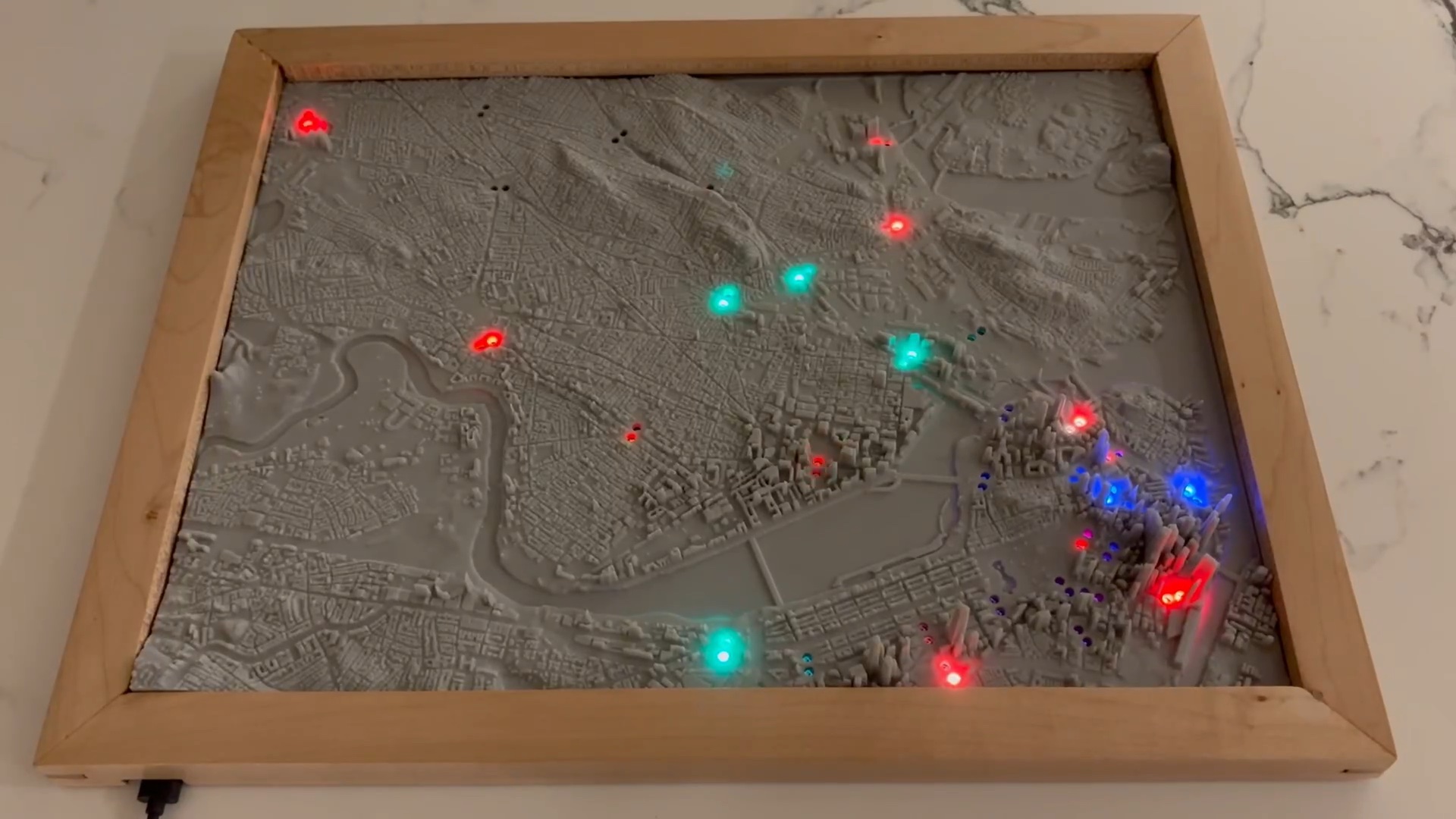
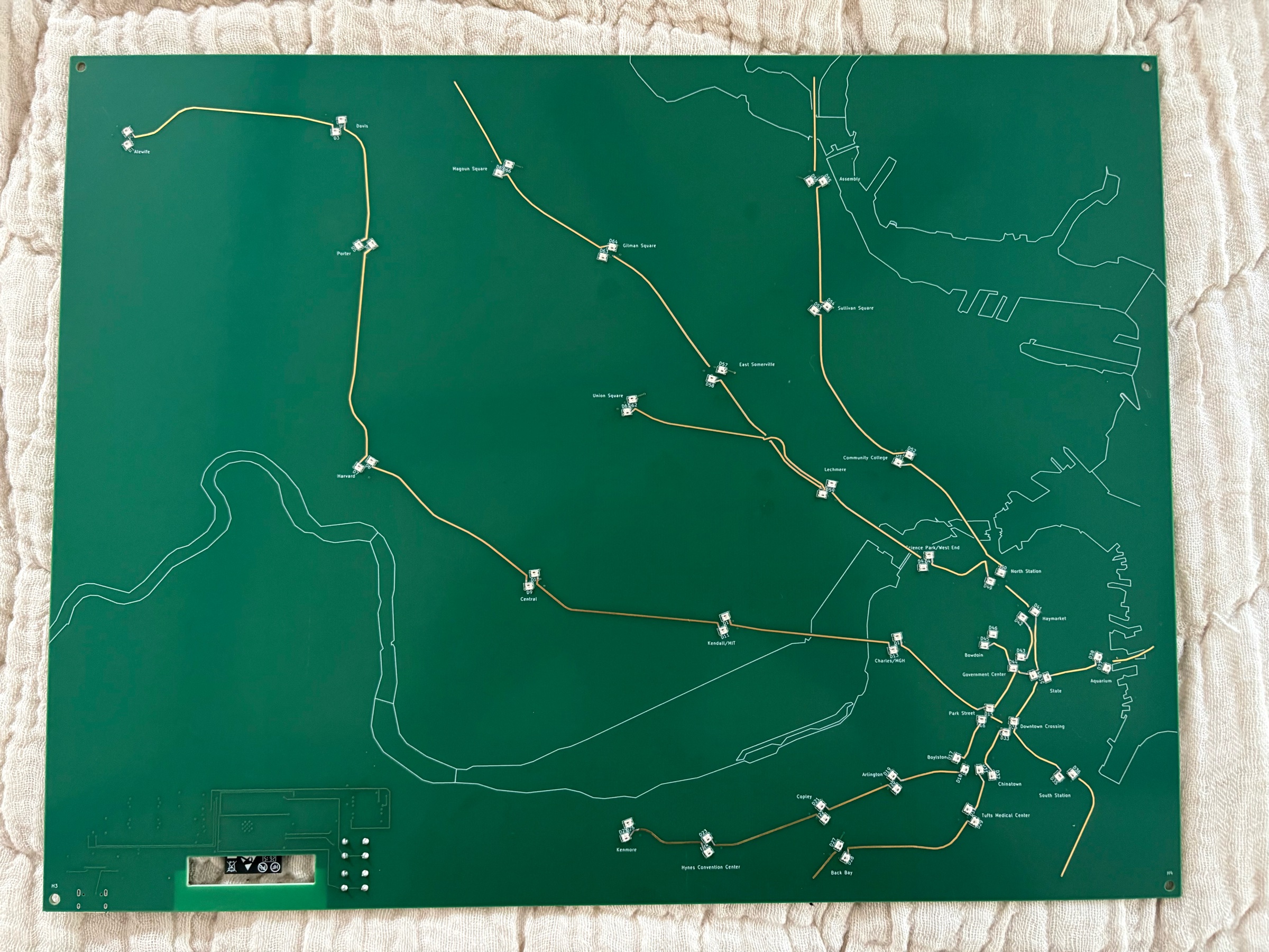
“And what exactly is it?” you might ask. A custom made scale replica PCB of a portion of the Boston MBTA public transit system, with color-coded LED pairs used to animate the various stations along each line and electrical traces highlighting the rails, all fed with live train data from the MBTA’s API. On top of the PCB is a 3D printed topographical map of the city with cutouts over each station.
Background
I’m not entirely sure where it comes from, but I love maps. Even more so if they’re scale renderings.
Maybe that was the latent inspiration for this project. I think the idea first germinated a few years back when I was looking at Christmas gifts and came across Metroboards. I loved the concept behind it but I found myself a bit disappointed that it (and the other implementations I found online) opted for the simplified version of the transit systems - the kind you see on information maps where every stop is equidistant and the lines are perfectly straight. That spurred my thinking: what would it take to build an accurate representation of a transit system on a PCB?
This wasn’t much more than the occasional idle musing for a few years, but when I built the Raspberry Pi header I wrote about last time and I discovered the rapid advances AI had enabled in PCB prototyping, it brought the idea to the forefront of my mind again.
Prototyping the LED Board
Though I’d recently done the Raspberry Pi header, my confidence in being able to accomplish something of this complexity was limited. As a result, I decided to build a more “standard” LED board as an intermediate stepping stone (and something that would be cool in its own right.) My hope was that this would let me de-risk the things I’d never worked with before like a Wifi module, power etc.
This was right around the time Fable came out (before the ban lol), and I decided this would also be a good chance to test drive the model to build out the schematic and do routing + placement. Coming from Opus 4.8, it was pretty remarkable how much more capable of a PCB designer it was.
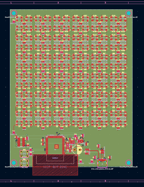
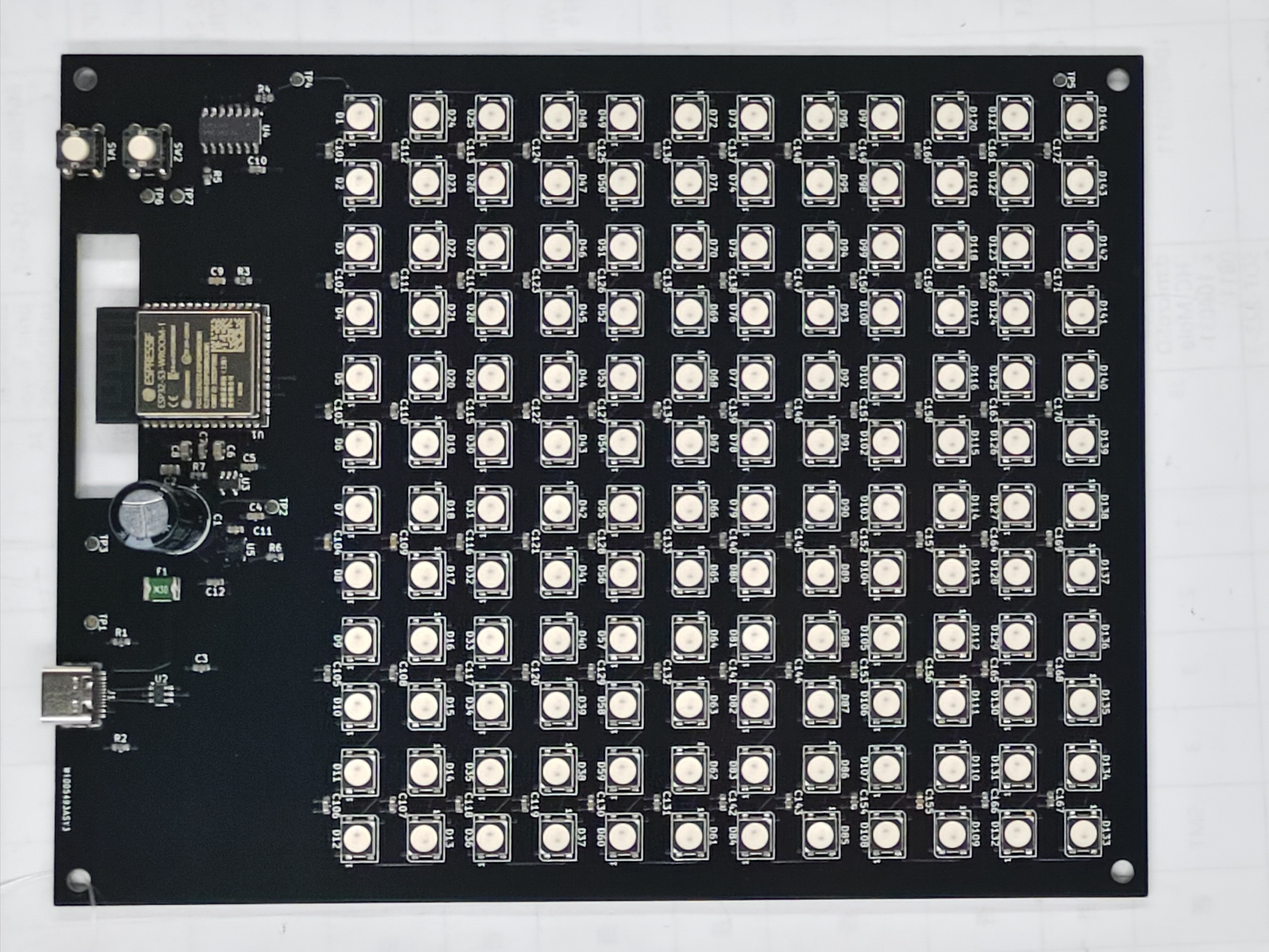
The only thing that didn’t work out as expected was that I’d added an accelerometer to the board so that I could do a “water slosh” animation, but I couldn’t get any data back on it. I suspect it was a shorted trace (to be fair the fabricator had told me it wasn’t within tolerance but I told them to yolo it nonetheless. Oh well.)
Also, I’m generally not a conspiracy theorist but I would be remiss if I didn’t mention that the speculation at the time that Anthropic nerfed Fable after the ban definitely holds water in my mind given my experience on this project using it on both sides of the release. Anyway. Moving on.
Building the MBTA as a PCB
With one board successfully under my belt and my confidence surging, I decided to start in on the real thing. My idea was simple: take more or less the exact same construction from my LED board, place every component minus the LEDs on the underside, and then arrange the LEDs in the correct places on the top side.
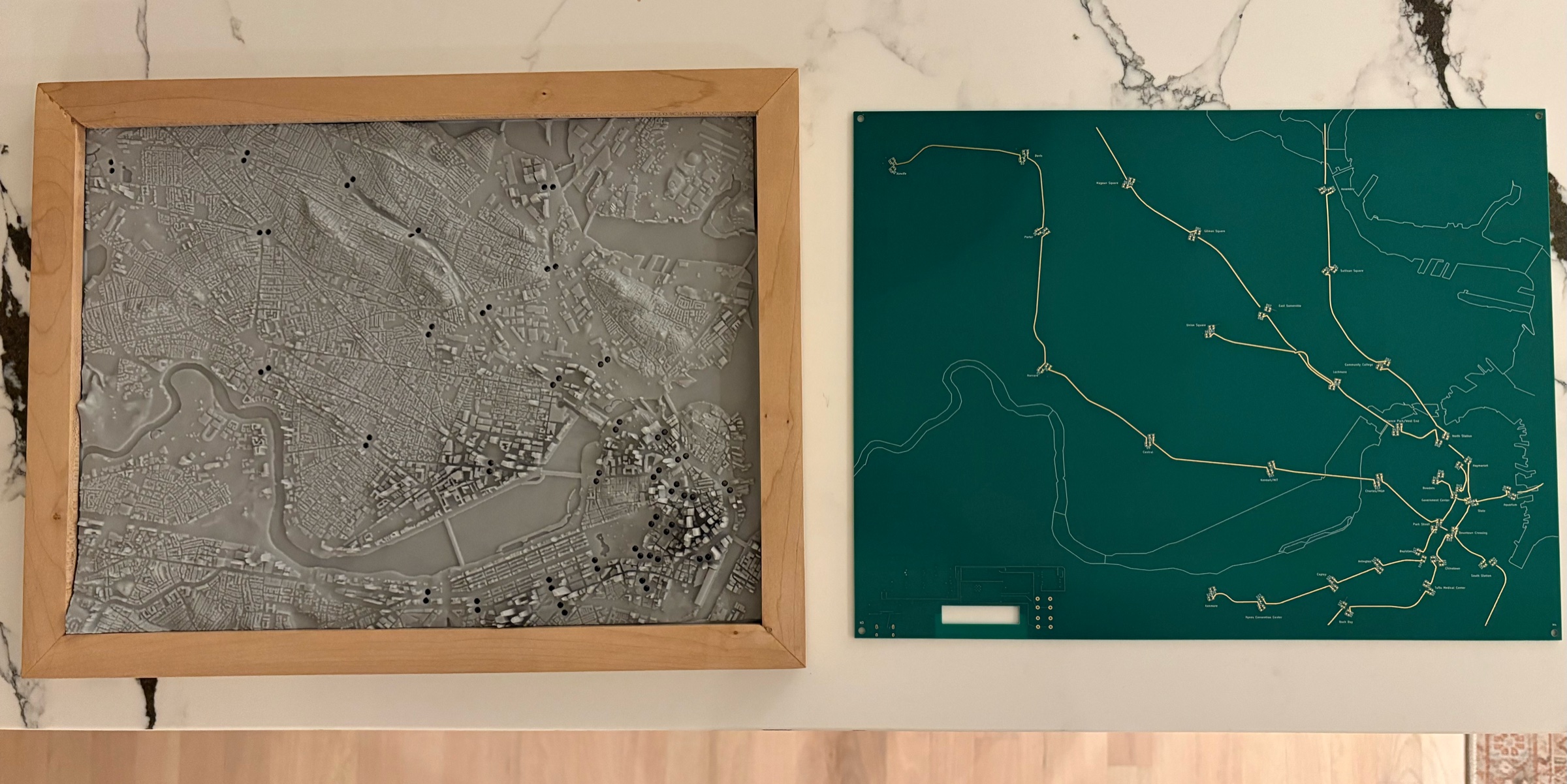
This process went more or less to plan at first, but after the initial pass things started to get a bit dicey. At this point I’d had to switch to Opus 5 to avoid exorbitant API costs, and the difference was noticeable in terms of routing. It started off strong but once we get to the 15th or so diode in the chain (out of 66), it started making worse and worse decisions and by the time it finished downtown it was a jumbled mess. It took a fair amount of fine tuning component placement and re-routing funky tracks before I was happy with the layout. What is unique about this board is that the traces themselves are laid out like the real MBTA lines. From an electronics standpoint this is nonsensical as the logical thing would be to make the runs as short as possible between the components. That was one of my favorite parts of this project, though: the combination of engineering and art. Additionally, though a simple trace would have been sufficient, I wanted it to really pop on the board itself, which is why I chose a gold mask overlay along the routes.
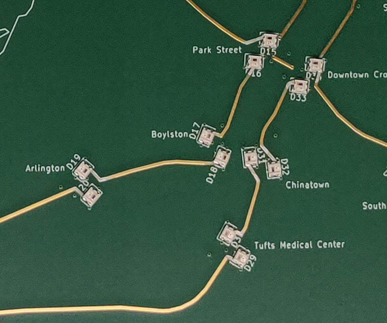
Once I was satisfied with the appearance, I sent it off to the manufacturer. A few weeks went by during which there was some back-and-forth over email with general questions about the board and component selection…nothing too out of the ordinary. Then the trap door swung out from under me. It started off innocuously enough: a routine question about the orientation of the LEDs. It seemed simple at first glance but the datasheet they referenced was written in Mandarin so it took a few passes through an LLM before the nature of the implications of the question started to dawn on me: the electrical pinout of the LEDs I had selected was fundamentally incompatible with what was fabricated on the board. But how? I’d built the prior LED board to try and prevent this exact type of thing from happening!
I did some investigation and here’s what had happened. On my prototype 12x12 LED board I had used WS2812B-5050 LEDs, which have kind of a chunky footprint and protrude from the board more than I’d like for this build. When I went to create the metro board, I opted for the much smaller, lower profile WS2812B-2020. I thought I had accounted for this while I was going through the board design. In hindsight though, something very pernicious happened: I correctly used the stock WS2812B footprint in KiCad for this part but in bringing over the electrical connections from the previous build, it used the 5050’s electrical wiring and NOT the 2020’s. So all my design rules checks passed but in reality my power and data lines were scrambled. So it was dimensionally correct but electrically wrong.
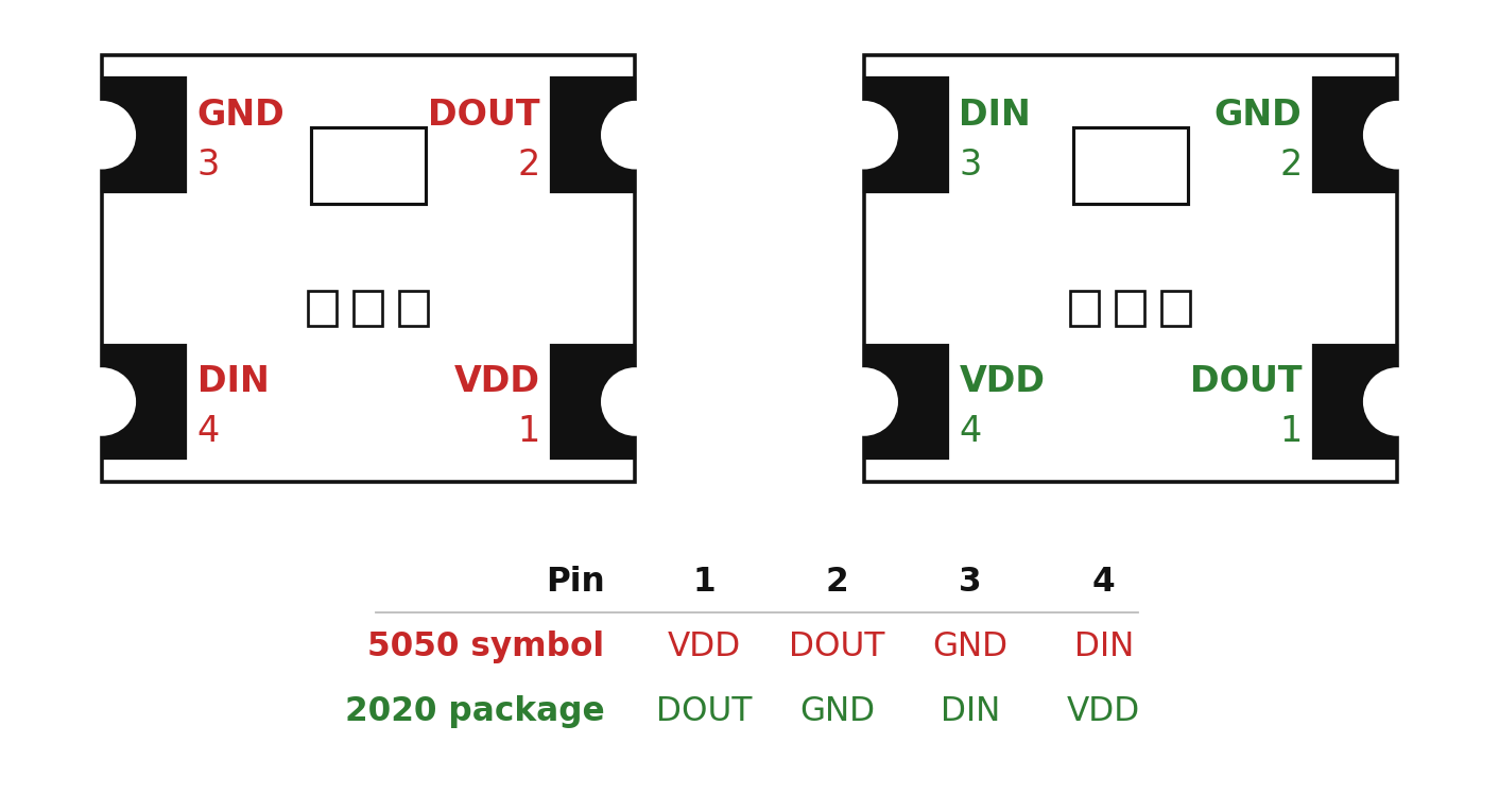
Ugh. After frantically researching for what felt like an eternity but was probably 10 min in total I gave up and sat staring blankly at my computer for I-don’t-know-how-long. Nothing to do but scrap the board, fix the symbol and resubmit. Sometimes you just have to learn the hard way.
Creating the 3D Map
I love the idea of 3D printing but my actual skill at it leaves a decent amount to be desired. I can do basic stuff in Tinkercad but that’s about it. One of the things I love most about SOTA AI (and their attendant harnesses) is that they’ve gotten realllly good at tool use. So in the span of an hour or two I can create something that would have taken me (quite literally) dozens of hours to learn how to do by hand.
That was certainly the case with this part. To draw downtown Boston/Cambridge/Somerville in a CAD software by hand would have been well beyond the pale of my abilities. Even scripting it would probably have been a multi-month side project at least.
The real action, then, remains in the judgement of what the end goal actually is. One of the first major decisions I had to make was: what scale should this be drawn at? It’s a little harder than it sounds. If you were to include the entire MBTA, you’d have a board with almost no vertical definition. It’d be more like the view at the cruising altitude of a commercial airliner. However, err on the other side of zooming in too close and you miss out on key features. I chose the section of the MBTA that had the most personal significance (the Red Line and downtown) and then, after a lot of finessing in Google Maps, landed on a ~1:23,000 scale rendering of a rectangle spanning from Alewife to just shy of Seaport.
Alright, with the boundaries staked out the question then becomes: what do you emphasize? This may seem paradoxical as setting a defined scale ratio would presumably make this question moot. However, we’re trying to create something visually interesting and not just scientifically accurate. Let me give you an example of what I mean. Boston is…flat. The total elevation variance is pretty limited - 30m max. So a true-to-scale topographical map is relatively uninspiring. To that end, I decided to double the vertical scale of the ground as well as creating an artificially large bank wherever there were water features (e.g. the edge of the Charles River or Boston Harbor).
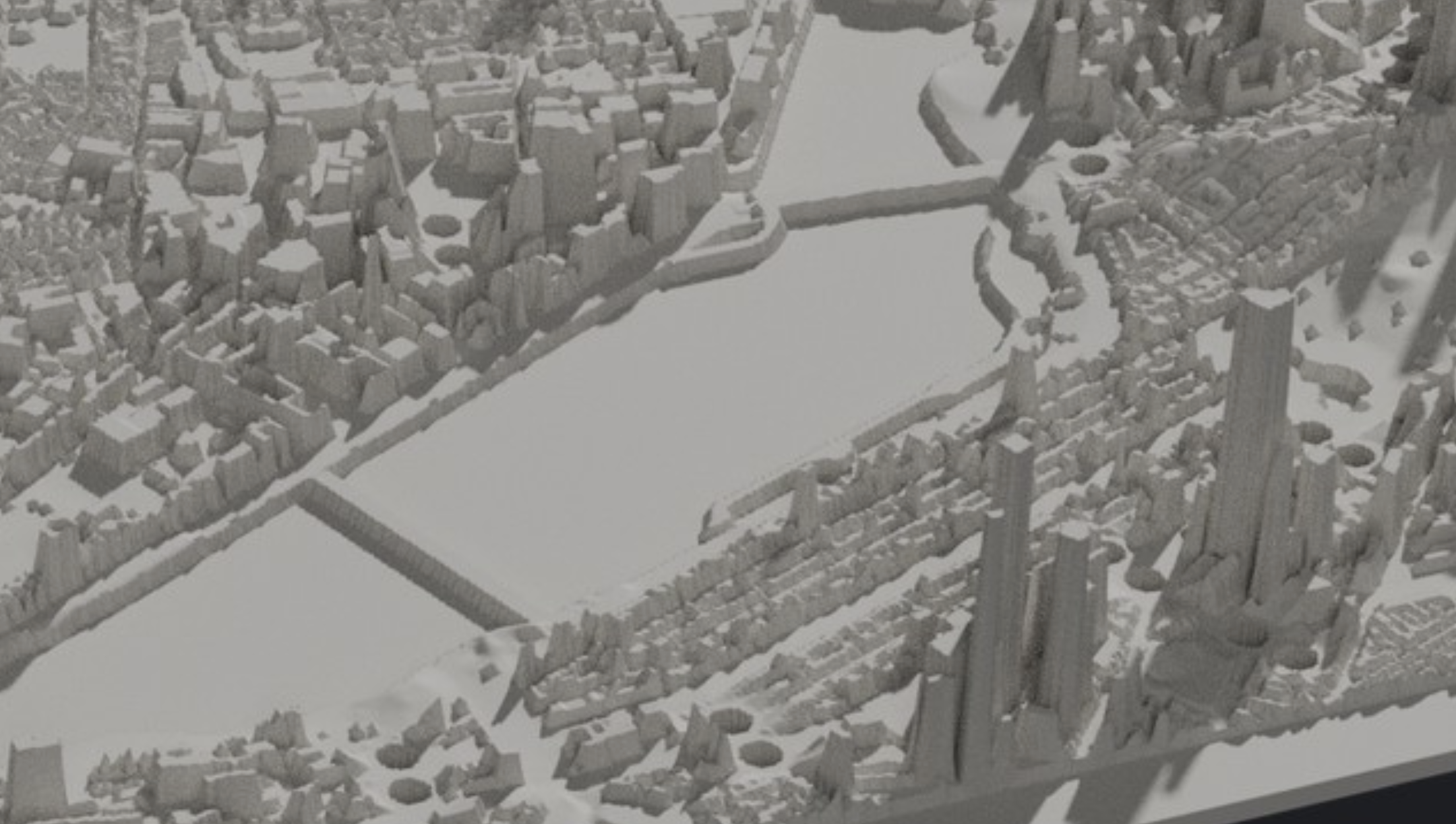
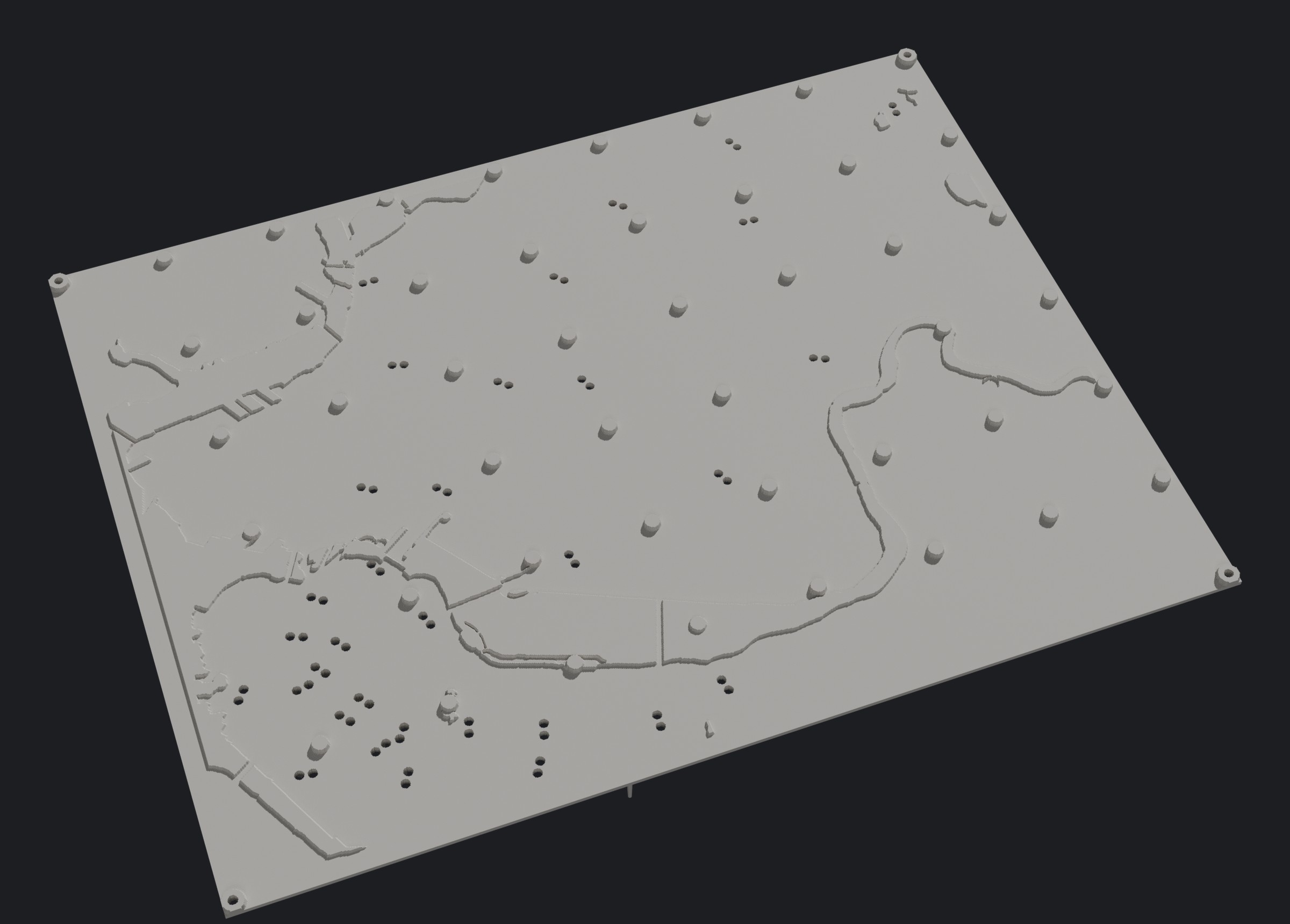
Quite a few minor tweaks later and I ended up with this:
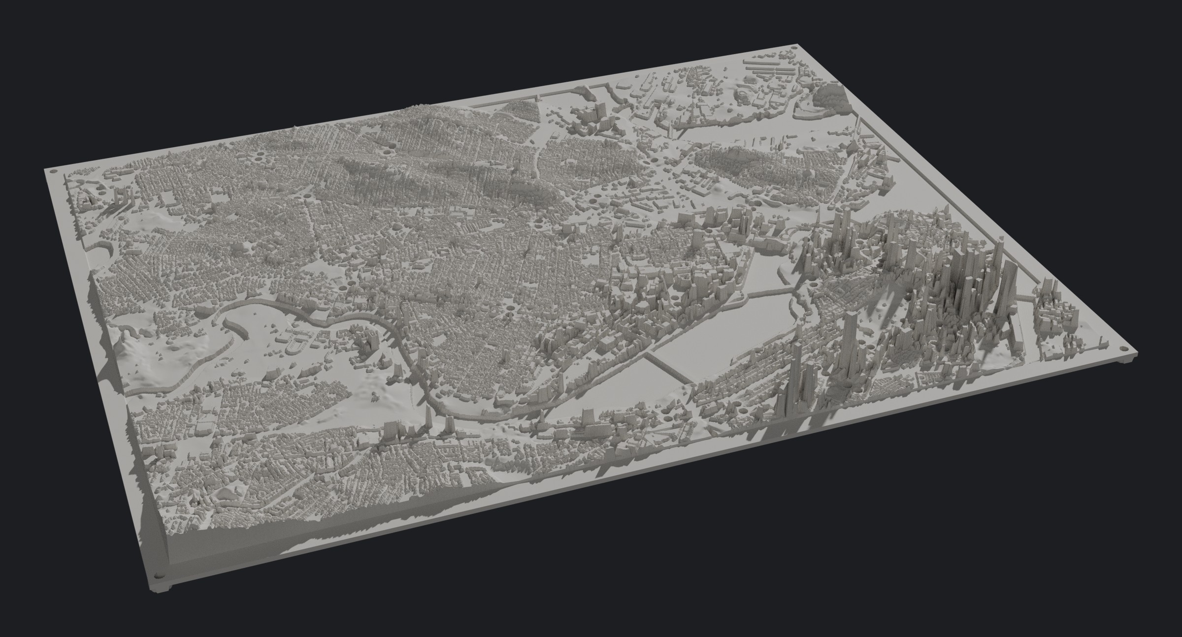
A few more interesting things: I had to scale the Longfellow and MIT bridges over the Charles to be MUCH larger than they are in real life, as true-to-life size would be below the 3D printer’s minimum printing resolution. If this were to scale then these bridges would be like a football field’s width (which honestly might have eased traffic if it truly were reality haha).
I also had to deal with the question: how do I handle buildings around the cut-through holes for the LEDs? I played around with a few different options (none of them particularly good) and finally settled on what I felt was the least-bad option: tapered buildings. Still funky looking up close but in real life it isn’t all that noticeable. Finally, to prevent sag towards the middle of the board I did small supports all throughout the underside of the print.
Making the Frame
I, in my ignorant hubris, originally considered this part of the project mostly an afterthought. A passing “Oh and I’ll make a nice frame for it with my scrap maple”. I was wrong. This ended up being one of the more time consuming parts of the project (though that’s in large part due to the fact that I’m a woodworking novice).
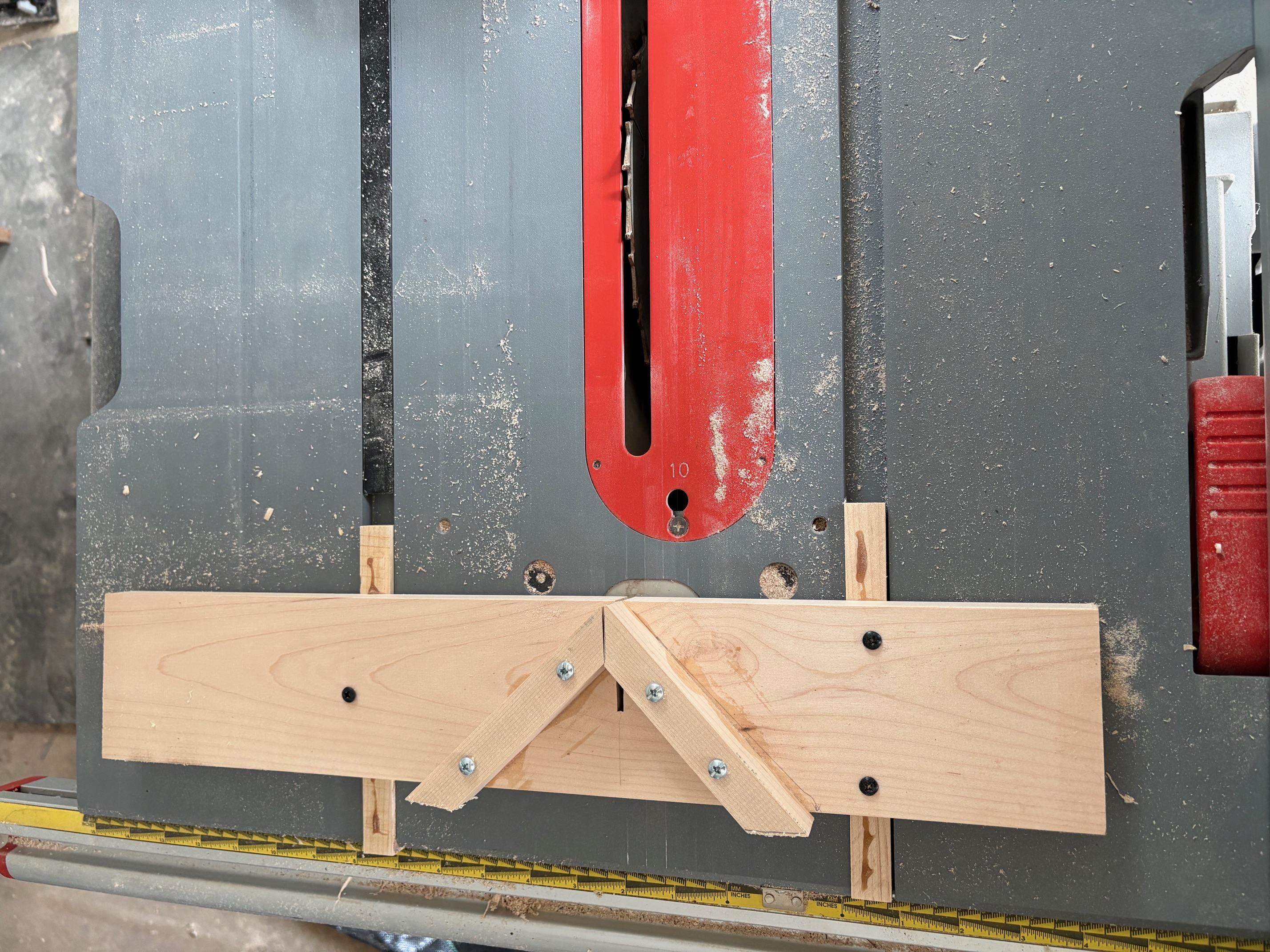
From what little woodworking I’d done previously though (i.e. my table-top trebuchet…story for another time), I did know that in order to get a frame that looked anything close to decent, you need extremely precise cuts on the angled joints - not the kind of thing I felt I could manage freehand on my mitre saw. In researching techniques, I came across instructions for a 45 degree table saw sled. The idea is that by setting your guide corner to a fixed 90 degree angle, it doesn’t quite matter if one side is 46 degrees and the other is 44 degrees because they will always sum to a perfect 90. The joys of geometry!
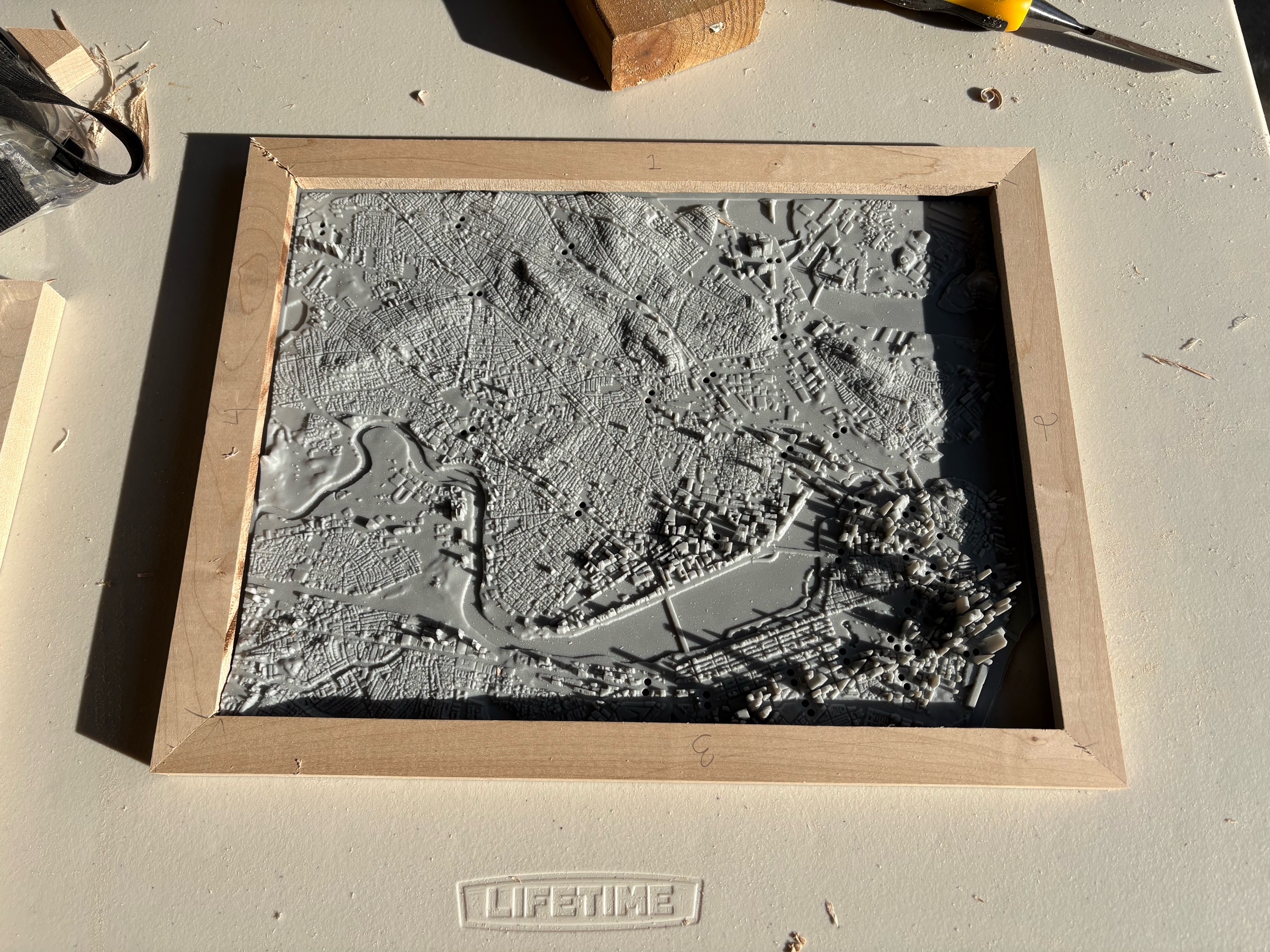
The next issue I faced was that I probably shouldn’t have put the screw holes on the boards where I did because they land exactly on the seam of the adjoining corners. Not the best design for stability. This was maybe overly cautious of me, but to beef up the strength of the frame at the corners I decided to cut a spline into each corner. I ideally should have created another sled to handle this type of situation but at this point I was getting lazy, so I just did freehand cuts on the table saw and it turned out reasonably well.
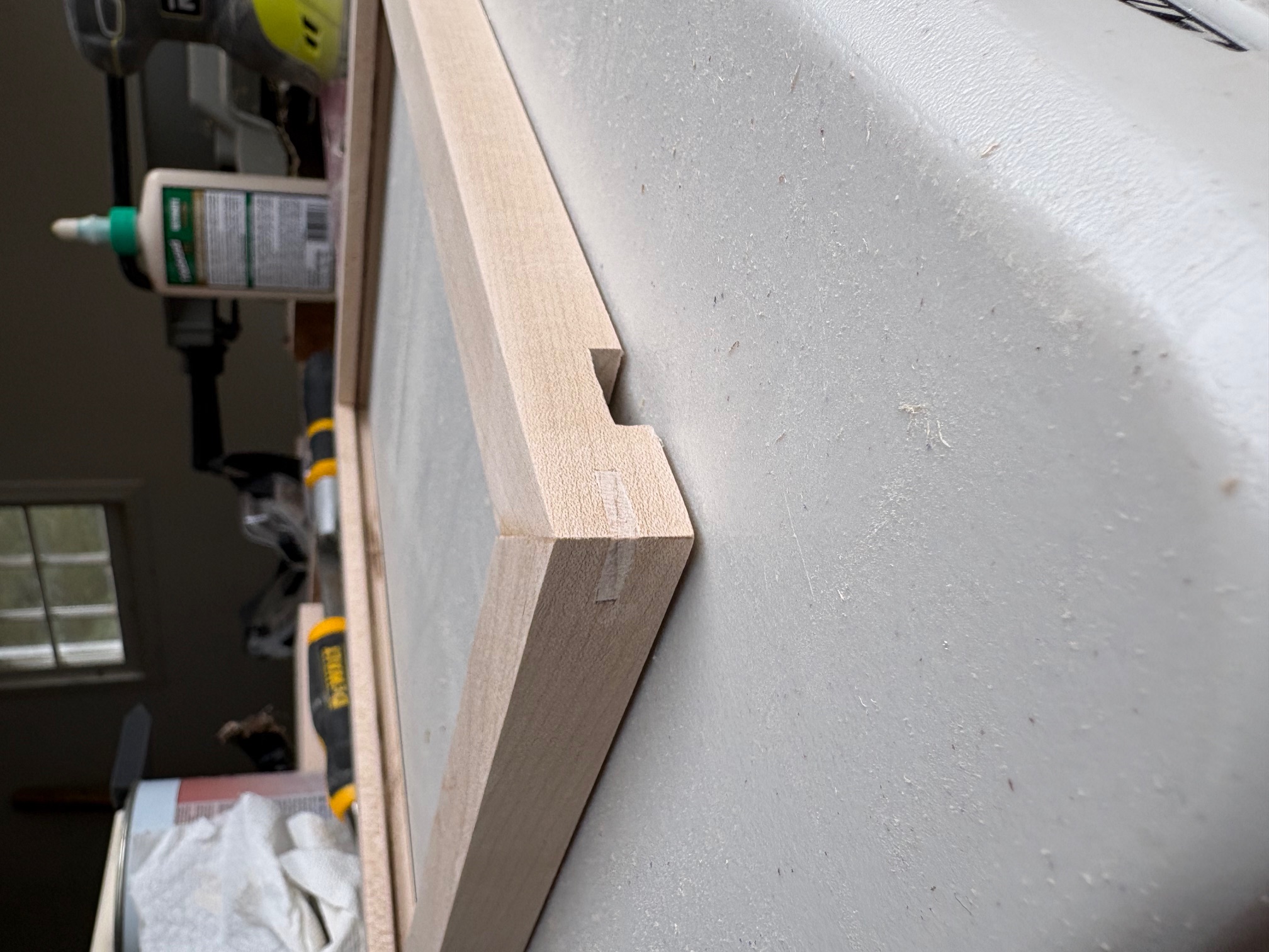
A few coats of shellac and polish in between and then it was all set!
And Now the Software
One of the miraculous things about AI-assisted engineering is that the concept of a “digital twin” is significantly more feasible. Modeling and simulation has always been technically feasible but I’ve never personally had the time, energy, or desire to learn the tooling necessary to create anything resembling robust simulation ahead of time. Not so anymore!
While I waited for the LED board and 3D Map to come in from the fabricators I had an extended Claude Opus 5.5 session where we built an “exploded view” simulation of the entire project, along with what the final animation of the trains ought to look like. It came out way better than I anticipated for what started out as an (admittedly) low-effort attempt.
I could probably write an entire blog post on the software design (maybe I will?). For now I’ll spare you most of the details and just offer a few high level thoughts:
- It’s oddly refreshing to operate in an environment where resource consumption is always top of mind and you have to think critically about the hardware you’re running on.
- In the same vein, I love the challenge of thinking through how an embedded system ought to respond to a variety of different scenarios. I often take for granted the amount of engineering and forethought required to be able to just plug something in and not have to worry about it for weeks, months, or even years. In this particular build this looked like many things:
- Partitioning the memory to be able to support side-by-side OTA updates
- Testing various OTA update mechanisms and failure modes. One of these actually did send my board into an electrical brownout…which is a bit of a misnomer because it blasted white light on every LED it could until the current gave out. It’s funny because in debugging this problem Claude casually mentioned “oh, by the way, this might have destroyed some of your LED drivers.” which was mercifully not true. Got to admire the flippant air which was given towards what would have been a catastrophic hardware failure (made all the more so as I only coughed up the cash to have one board fully built).
- Setting up graceful transition between live data and simulated trains, with logic for falling back into standalone access point setup-mode.
- Figuring out ways of “hiding your delays” is always an interesting problem from a design standpoint. An example I’ve oft heard referenced is that elevator rides in a video game are usually just a cover-up for a loading sequence on the backend. Within this project, I needed the board to be doing something while it ran its first poll of the live MBTA data. Ultimately I landed on a fade-in-fade-out sequence which at first seemed like a necessary evil but once it was implemented I felt like it would have been lacking without it.
The Finished Product
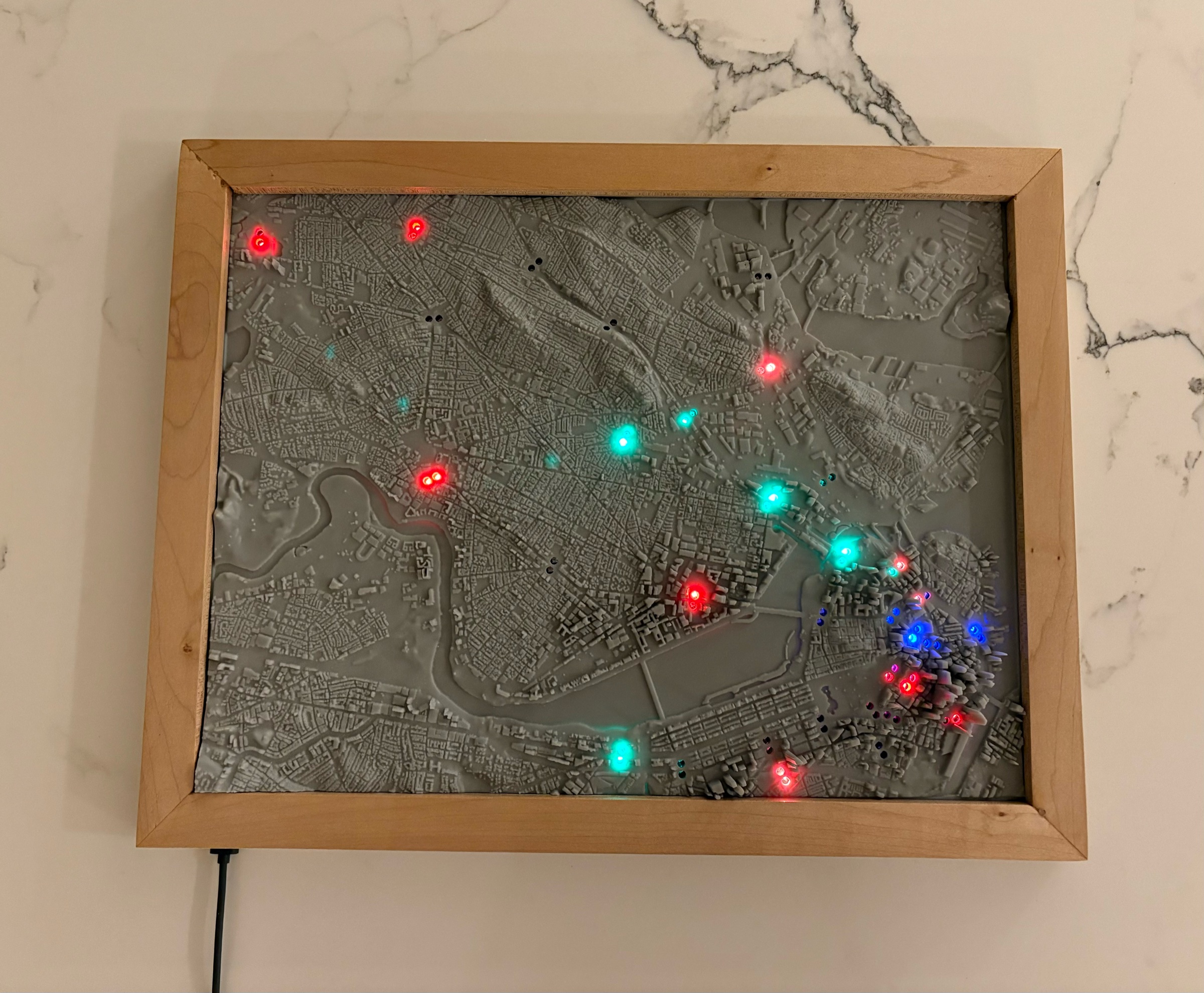
As with any good project, I find that finishing it is a bit bittersweet. If nothing else, at a moment in time where there’s huge emphasis on using AI to maximize output, I hope this serves as a small reminder that there is still immense value and meaning in creating things simply because they are beautiful.