“This feels fundamentally different…”
That was my immediate thought the first time I watched Claude Opus 4.6 successfully one-shot a complex problem. I was having a harder time finding the limits of what it was capable of.
This naturally spurred my second thought “…but can I use it to build hardware?”.
The verdict:
pretty neat
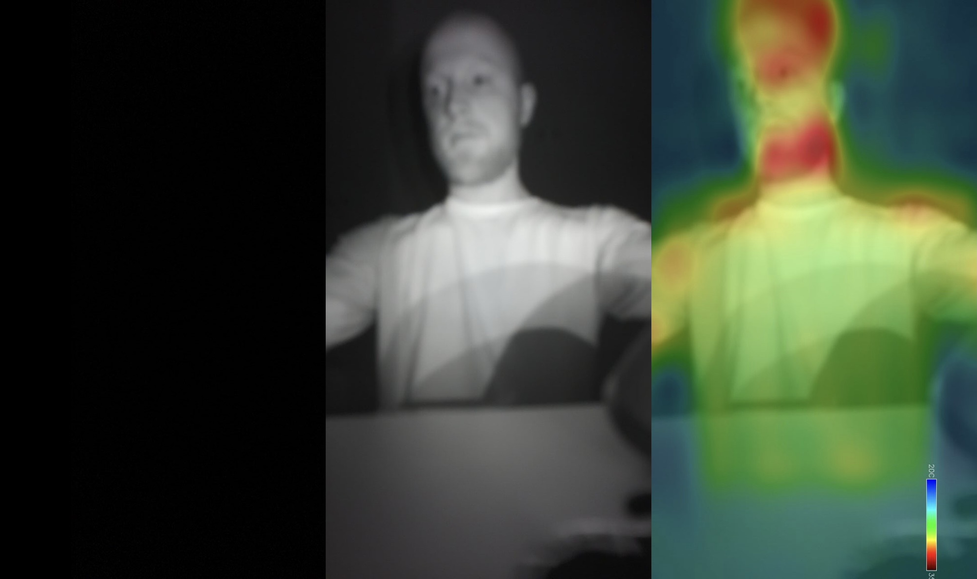
it can do night vision! and thermal!
Read on if you want to know more about how (and what) I built in this project!
Background
The inspiration for this project actually started quite modestly and without any custom hardware aspirations - I found this tutorial1 online for building a thermal camera overlay with a Raspberry Pi and I wanted to try it out for myself.
The more I got into it though, the more ambitious my aims became.
What if I could have it do license plate recognition too?
What if I wanted to add night vision?
Well, if I’m adding IR LEDs, why not add an IR receiver too?
The scope of the project and my latent desire to see how far frontier LLMs could take me on hardware design/builds helped me land on this:
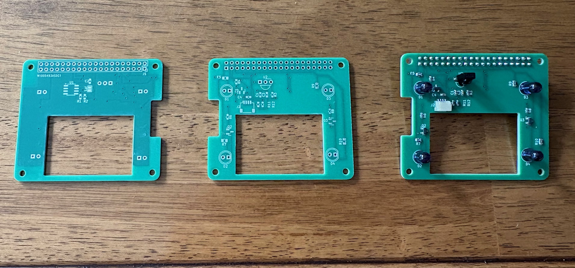
A Raspberry Pi custom headerboard containing IR LEDs (for night vision and remote replay), an IR receiver (for capturing remote codes), and a Stemma QT type connector (for more easily attaching the thermal sensor). These components, combined with both a standard and NoIR camera (the Pi 5 supports dual cameras) would then round out the sensor array for my multitool.
Getting Started with Hardware
I’ll be honest, the last time I designed a circuit board was in 2017. The entire landscape has changed dramatically (not to mention my skills have atrophied significantly). I was surprised though at how readily several of the concepts came back to me - particularly with the in-depth explanations from Claude. PWM. Pull-down resistors. Decoupling capacitors. EEPROM. All terms that I’ve given very little headspace in the almost-decade since I left college. I was surprised at the level of joy that reintroduction brought.
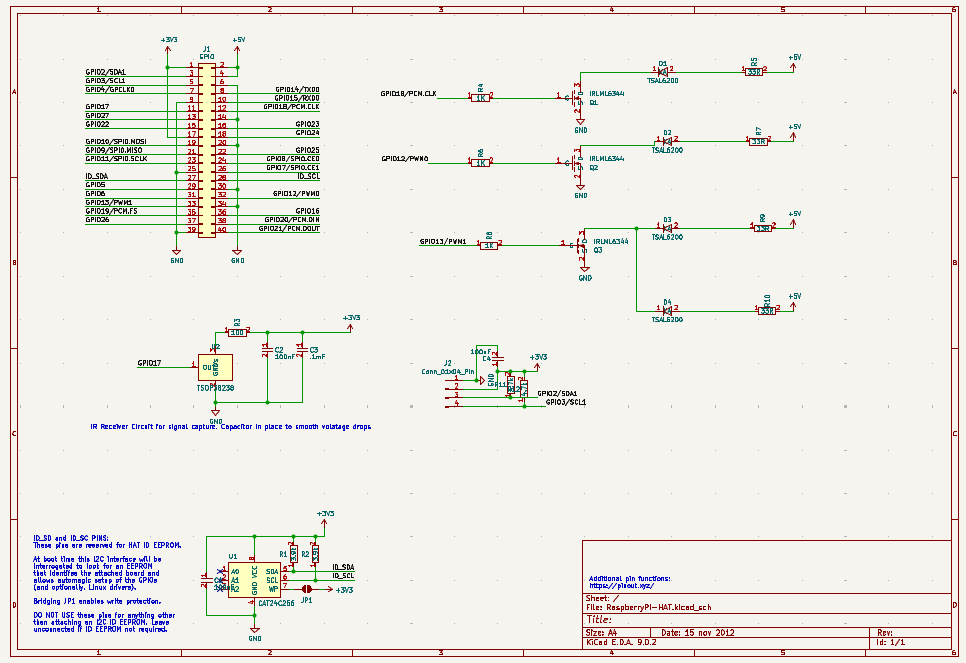
I started by having Claude generate a Kicad schematic. It was…not great, but it had several of the necessary components and the circuit was coherent. That was the first general lesson: it’s great at theory but struggled with raw implementation.
After cleaning up the schematic quite a bit and running a few simulations, here’s what I came up with:
Then it was on to PCB design and routing. There is an existing Pi header PCB outline already published, which was quite helpful. In reading up on PCB design I saw several folks reiterate the idea that it’s 90% component placement and 10% routing.
Being an impatient lad though, I clipped through the component placement rather quickly and paid for it later by having to constantly adjust footprints as well as doing some wacky routing right at the end.
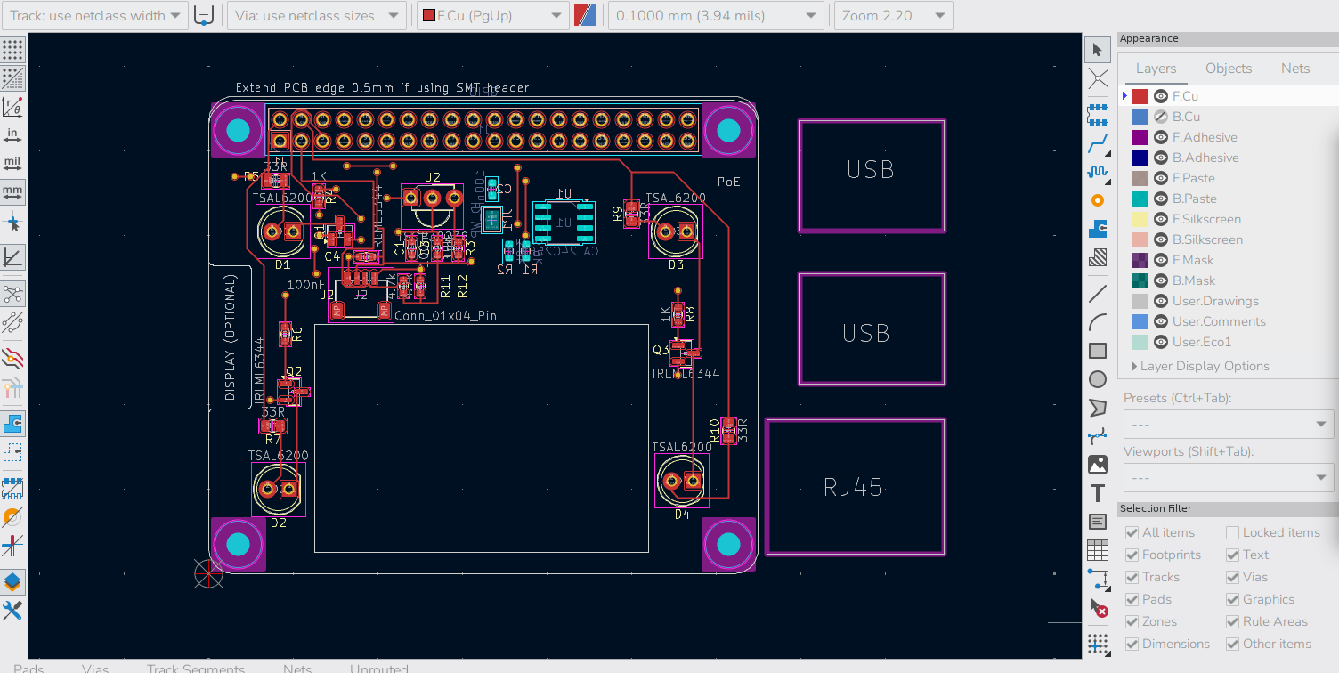
I wish I’d taken more “work in progress” pictures. It was a labor of love in many ways, but routing is one big puzzle, and that aspect really appealed to me.
I also challenged myself a bit by having a fairly decent sized cutout in the board to allow for the camera ribbon cables to feed through, as well as to help with cooling. This reduction in real estate forced me to redesign the board a few times but oftentimes those types of constraints can force you to get creative in ways that you wouldn’t normally otherwise have to. In the end I was able to get it all to fit.
Once all the pieces were in place it was a constant back-and-forth of running the Design Rules Check and cleaning up the errors and warnings. I had forgotten to do a groundpour which solved a lot of my problems and there were a few issues here and there with footprints being too close together and other stuff.
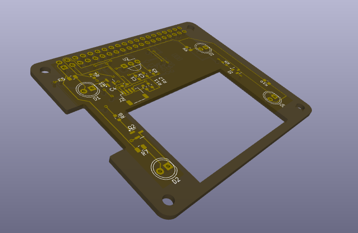
Kicad has a cool 3D renderer at this stage:
Then, it was ready fabrication! I had zero desire to hand-solder tiny surface mount components, so I opted for the full service fabrication (still rather cheap all things considered). This is the part where Claude really shined: I told it to build me the component BOM and cross check it with real suppliers and make a unified list of component part numbers with their suppliers. BAM. First shot it gave me a tidy list with all the component numbers from actual suppliers that was accepted by the vendor. This would have taken me at least an hour or two of muddling through things had I gone at it alone but it was done in 5 min.
As an aside, does anyone know of a US-based company that does full PCB prototyping and fabrication? Seems like all the major players are in China.
Anyway, away it went for fabrication and I sat back and hoped that I hadn’t made some dumb mistake that would render my board useless upon arrival.

One final rabbit trail on the hardware: the board includes 4 slots for IR LEDs to provide night vision illumination (and remote code replay). For IR LEDs you have a choice of two wavelengths: 850nm and 940nm. 850 has better range and brightness for a night vision camera but there’s a tradeoff: it lets off a faint red glow in the dark. It’s kinda creepy looking and alerts you to their presence 2. For that reason I chose 940s for this project so that it would truly be undetectable to the naked eye.
Software and General Project Details
While the PCB was being fabricated, I started working on the software side of things.
At a high level, the Raspberry Pi runs a FastAPI server which the user connects to via websockets. The server registers all of the various sensors and cameras as singleton instances upon startup, allowing them to be individually added to the sensor registry.
At this point, the only sensor I had was the NoIR camera. I got it wired up and registered and started to play around with basic object detection, followed by license plate detection. However when I took the Pi over to the window to test it on my car’s plate…the screen was utterly blinding. Totally whited out. Which makes sense given that the entire point of this camera is that it has no IR filter…meaning it gets completely blinded by ambient daylight.
When I was first working through the design of this project I thought about trying to get a camera with a motorized IR cut filter (so that I could toggle between day/night mode with a single camera3), but I already had a standard Pi camera, so just upgrading to a Pi 5 which supports dual cameras felt like the smarter move. In hindsight this was a serendipitous decision because the price of a 16GB RPi 5 went from $200 to $300 a few weeks later due to the exploding cost of RAM. Ooof.
At this point I’d also gotten my hands on a thermal sensor, so I was able to begin experiment with not only using multiple cameras, but also layering on the thermal sensor visualization.
I used the widely available MLX90640 thermal sensor for this project. The thing about thermal sensors is due to the underlying physics and their implications on cost, the sensors are rather low resolution (this one is 32x24 for a grand total of 768 pixels). However, they can be quite sensitive - registering to within .1 degree C per pixel. Here’s the actual raw output of the sensor:
![]()
Laughably small right? The aforementioned sensitivity of the pixels allows us to get creative on the software side though. First, we can “expand” the image to achieve much larger resolution. OpenCV has several algorithms for doing this - here’s a side-by-side comparison of some popular ones:
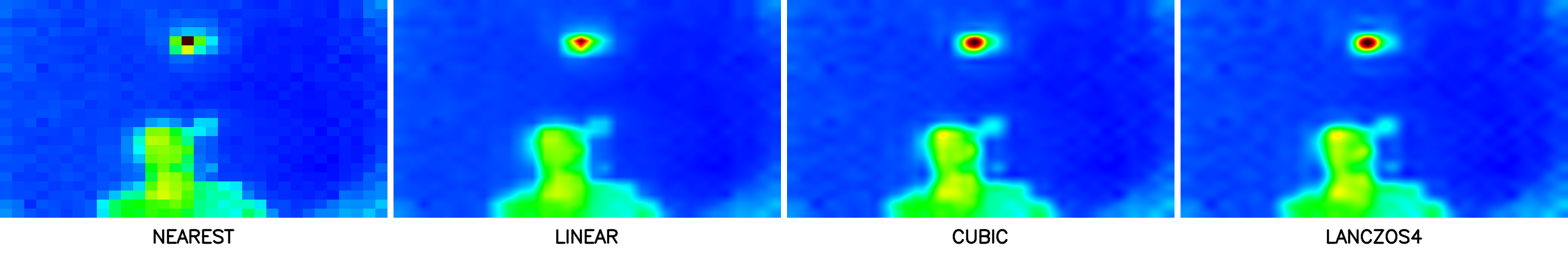
The tradeoff here is computational complexity, which roughly increases as you move from left-to-right. Now that we have a larger image we can run a smoothing algorithm so that the image looks “cleaner” and adjust any block-i-ness of the pixels.
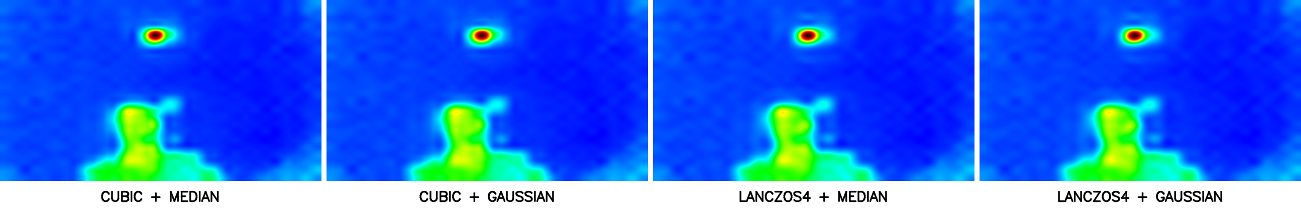
In reality, most of the heavy lifting is done in the interpolation phase as the expansion smooths the gradients to begin with. So a 5x5 Gaussian blur for example is just mostly nudging pixels that already more or less look the same.
At this point, the UI buildout is highly customizable relative to the specific needs of the operator and the ways in which they would like to visualize this data. For example, my home screen provides both the camera inputs as options, along with any overlays the user desires (thermal, basic objects, license plates etc.)
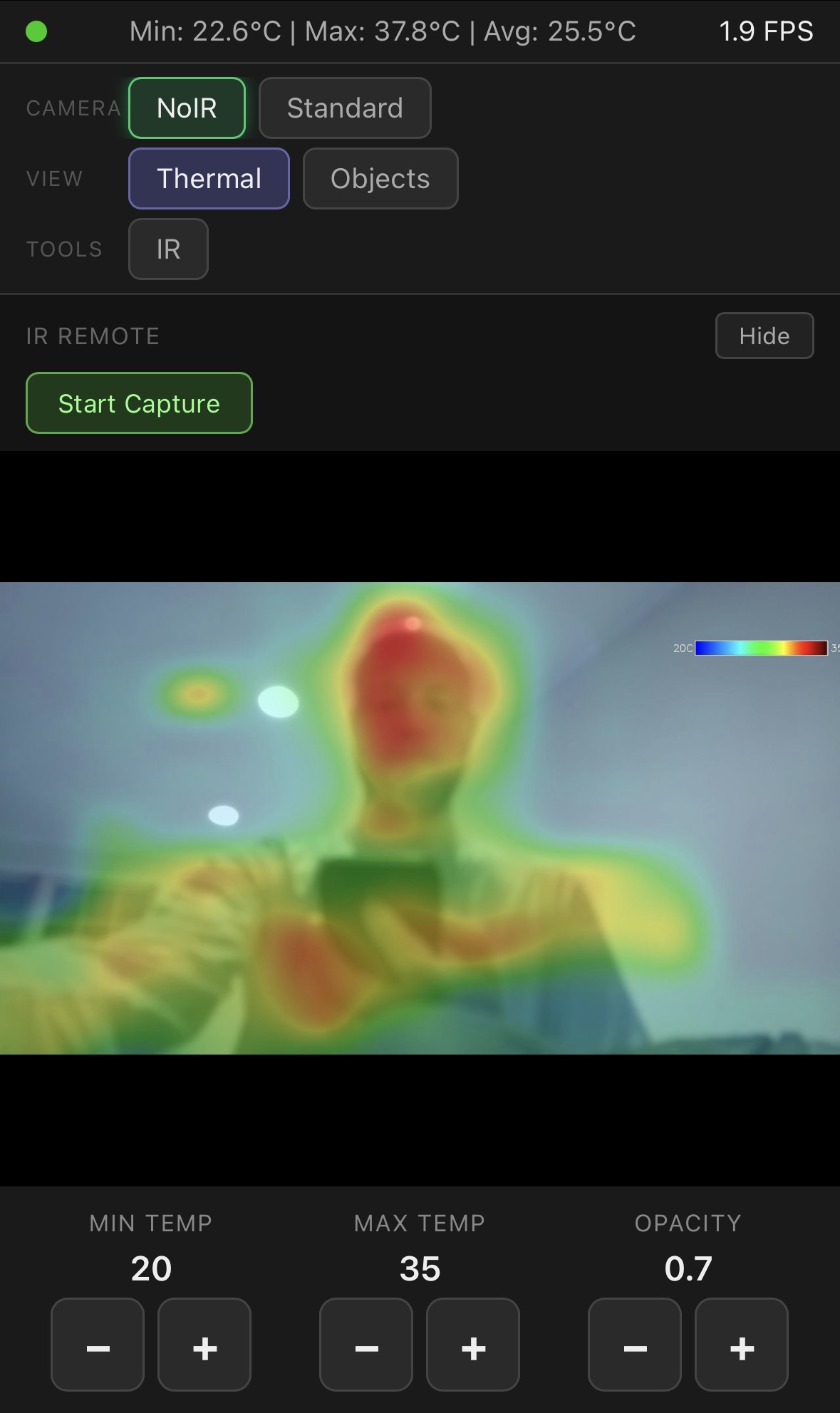
One of my favorite parts of this project is the countless ways you can combine the components. In addition to providing night vision illumination, the IR LEDs can also be used to flash remote control codes (that’s part of the reason I also put an IR sensor on the header). To make use of this feature, I also added a capture/replay portion to my frontend: you start a capture, press a button on the remote you want to clone, and the software captures and displays the signal.
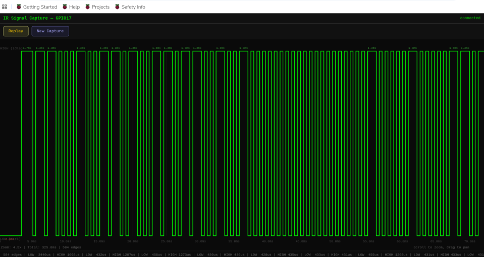
Then you can replay the signal or save it for longer term use. A cool future addition would be a “virtual remotes” section where the screen renders a picture of the actual remote you’ve cloned.
So, can AI design and build basic hardware yet?
The short answer is: definitely not unsupervised. While it’s remarkable it can generate schematic files to begin with, it was very reminiscent of how early gen LLMs were at coding: impressive for their time but pretty serious shortcomings.
The old adage that “everything easy is hard and everything hard is easy” really rings true here. Claude was a huge help on some of the circuit design theory questions where I would have felt a bit over my skis otherwise (things like groundpours, decoupling capacitor values etc). On the flip side though, it struggled mightily with things that felt trivial to me…at one point it thought for 20 mins and then gave up on a very simple trace routing issue that I solved in about 6 seconds.
All of this makes sense when you consider the underlying mechanics of an LLM. It’s read every electronics manual/textbook and every publicly available Kicad file in existence, hence it’s ability to nail common questions and build plausible schematics. Yet it can’t visually grasp the actual implementation in the way that you or I can - only the concepts as they can be described.
That’s all cool and stuff but this is seeming like another one of your useless projects Caleb…
Fair enough. There are certainly easier ways to do this than building a custom headerboard. BUT, I love this concept of a multitool.
Imagine that your car is having trouble and you have an OBD sensor lying around. You could plug in the sensor and use the Pi’s bluetooth module to read the codes. Then, you could pop the hood and snap a picture with the thermal overlay enabled - that lets you gather the visual inspection along with any temperature abnormalities. You could also plug in a usb mic to record the “weird sound” that your car is making. Finally, you could feed all that data to an AI agent and I’d bet a handsome sum that it could not only narrow down your problem significantly, but it could probably also either refer you to a local mechanic or show you the exact part you need to order and instructions on how to replace it. What a time to be alive.
Or, you could point the cameras at your neighbor’s window and set it up to send a “TV Off” remote code every time they turn on the TV. But that would be truly diabolical.
Wow, someone actually read this far.
I have an extra fully-built headerboard and 3 basic PCBs without components which I’ll gladly donate to the first person to ask me nicely ;)
Stuff I should probably be too embarrassed to admit
- My only personal development devices right now are Raspberry Pis.
- Worse yet, at the start the only available Pi I had was a RPi 4 with a measly 1GB of RAM. It held up surprisingly well through the initial camera work though it was making HEAVY use of swap. I could even run Kicad with it (albeit somewhat laggy)!
- Claude Code claims it needs 4GB of RAM, so at first I spun up a VM in GCP and would turn it on right before any of my coding session and right off afterwards. That was a colossal pain (as you can imagine). I really should just buy a quality laptop…but the aforementioned cost of RAM is making it a hard sell.
Stuff I am not the least bit embarrassed to admit
- I manually wrote every single word of this post. Nary a hint of AI. Savor every grammatical error as evidence of its authenticity.
- I did zero physical prototyping of this board prior to fabrication. I viewed that as part of the challenge: could I one-shot an (albeit simple) prototype using only software. In the end it was extremely rewarding to see all headerboard functions “just work”.
Footnotes
-
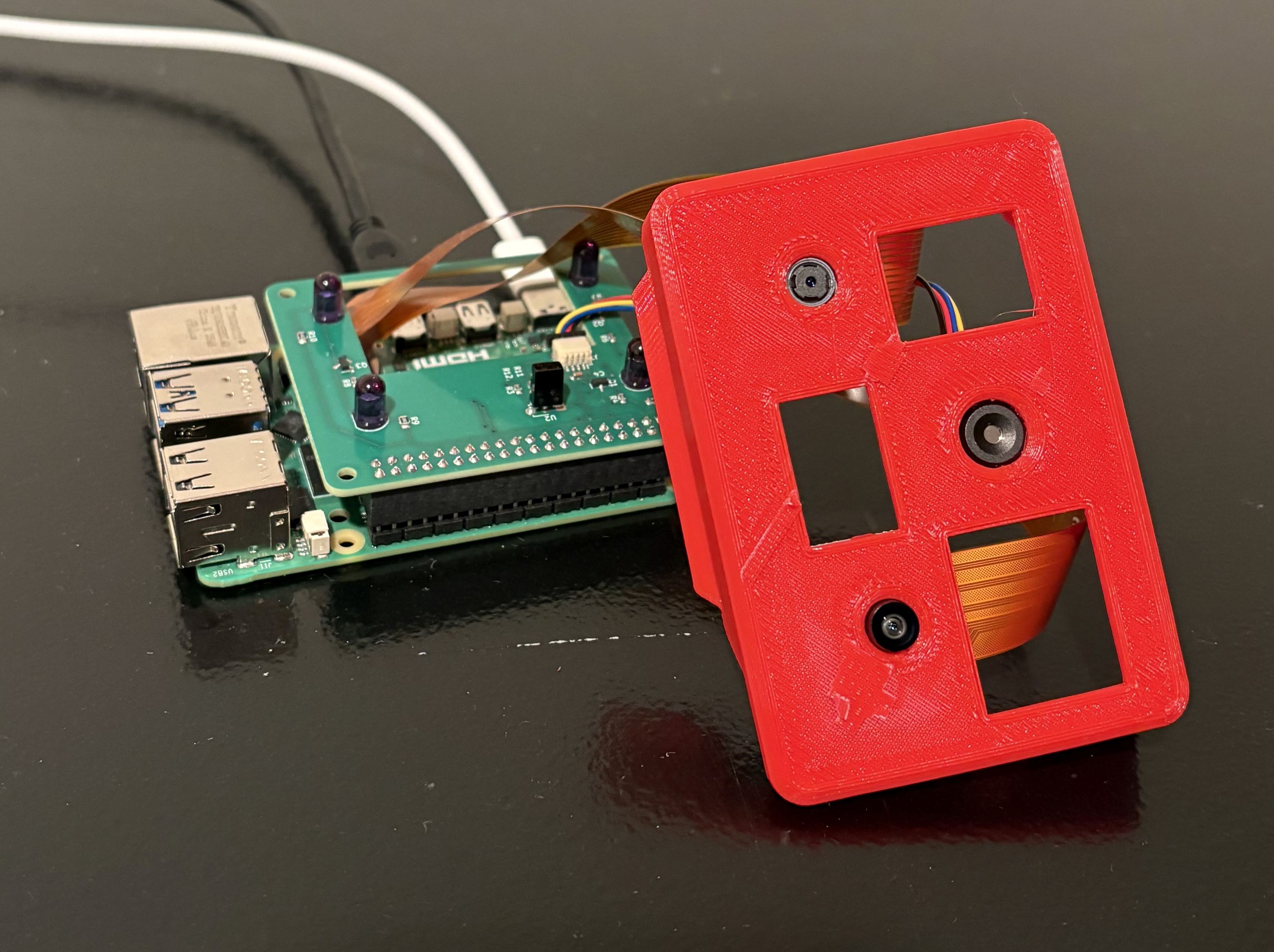
I got the 3d printed case from this project as well. I made some (admittedly pretty hacky) edits to shift the lens locations and add a second camera mount. ↩
-
This immediately explained why our baby monitor has 4 faint red dots when the lights are turned off: it’s the IR LEDs projecting. It’s rather ominous looking to be honest. ↩
-
It was in researching dual-mode cameras that I had the epiphany that this is exactly what the little “click” noise is when our baby monitor switches between day and night mode: the IR cut filter snapping into place. Man - learning lots about our baby monitor in this project… ↩