Pi Robot Prototype
Ever since the old days in the electrical engineering lab in college, there's always been something about embedded projects that has been compelling to me. Maybe it's the physical manifestation of the power of software or the creativity involved in engineering solutions that work in resource constrained environments. Whatever the reason, I'm always looking for new projects with which to explore the field further.
That's why when I saw this Pi-controlled robot, I knew I wanted to try my hand at something similar.
Concept and Design
My initial design was to build a Pi Zero based robot with four axels and a tread connecting each set - essentially a miniature tank. I did some research online and found the following set of 50-1 ratio motors and wheels/treads from the Pi Hut.
I suppose I should have paid slightly closer attention to the dimensions and pictures, but one of the trade-offs (for me at least), is that given all the peripherals necessary for this robot to function, the robot ends up being wider than it is longer. Not exactly very "tank" like. It's also worth mentioning two lessons learned here about the motors. First, these guys are tiny - not exactly a couple of powerhouses...which is fine for the scope of this project, but you probably want something more bulky if you envision this thing operating in anything more than level hardwood floors. Second - buy a mount for the motors. We'll get into it later but after lots of futzing with Krazy Glue and ill-fitting metal brackets, I can attest that it will be worth the small extra surcharge.
I already mentioned it, but for the controller I went with a Raspberry Pi Zero W - if you haven't seen from my other blog posts, I'm a big Pi fanboy and the Zero is no exception. Small, nimble, but capable of just about everything for the scope of this project.
Yeah, yeah, whatever. Let's get to the real engineering part.
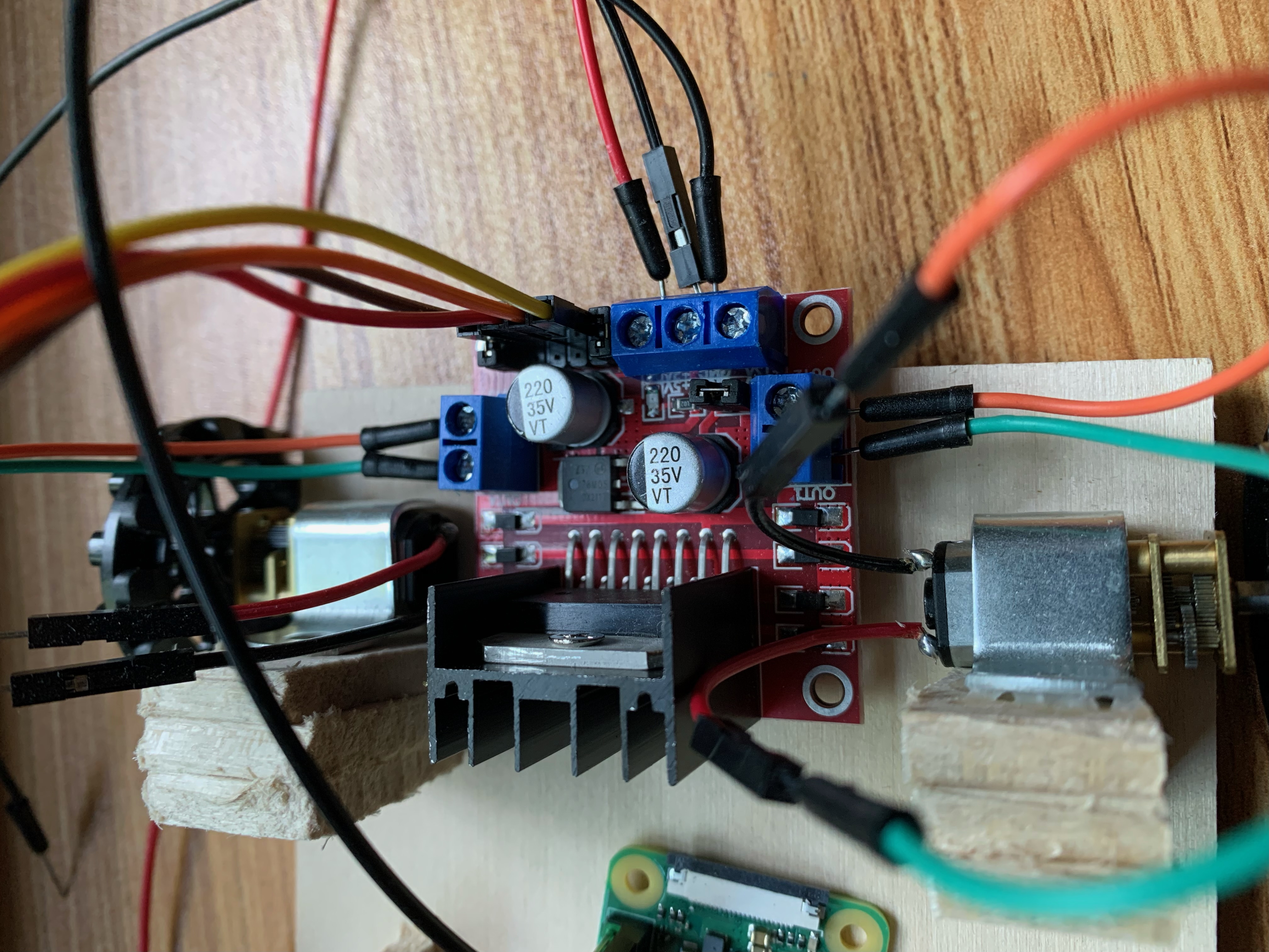
The first item on my agenda beyond buying basic components was selecting a driver that was suitable for the task at hand. I ended up going with the bulkier L298N. Dude's got a serious heatsink. There are plenty of other options out there (most with much smaller footprints) but because I was trying to minimize the amount of soldering in this project, I went with this one.

Getting Started
With all the parts in place, the first step was to get the motors spinning. I wish I'd had the presence of mind to take a picture of my breadboard setup so a word picture will have to suffice. I selected GPIO ports 23,24,25, and 26 to act as my + and - terminals for each of the motors. I wired each of those up to IN terminals for the A&B motors and then connected the OUT leads to 4 red LEDS, that way I could mimic the 4 different configurations of motor spinning (drive, reverse, left rotate, and right rotate).
I opted to use the Python GPIO library because of how easy it was to set up. If I were going to make a production robot I'd probably use C but for the purposes of this project Python was the way to go. Here is the example code I started with:
import RPi.GPIO as GPIO
import time

GPIO.setmode(GPIO.BCM)
GPIO.setup(23 , GPIO.OUT)
GPIO.setup(24 , GPIO.OUT)
GPIO.setup(25 , GPIO.OUT)
GPIO.setup(26 , GPIO.OUT)

while True:
  GPIO.output(23 , GPIO.HIGH)
  GPIO.output(24 , GPIO.LOW)
  GPIO.output(25 , GPIO.HIGH)
  GPIO.output(26 , GPIO.LOW)
  time.sleep(1)
  GPIO.output(24 , GPIO.HIGH)
  GPIO.output(23 , GPIO.LOW)
  GPIO.output(26 , GPIO.HIGH)
  GPIO.output(25 , GPIO.LOW)
  time.sleep(1)
Simple as that. Python 1, Other Options 0. Essentially this just verifies that we can toggle the GPIO status high and low for our desired output pins. We should see alternately flashing LEDs (and after a small amount of tinkering with the jumper cables) which is exactly what I observed. While this is a relatively straightforward example, it demonstrates the core functionality. Obviously the final project will have much more complex logic to allow handling but I took comfort in knowing that the electricity was flowing as expected.
To futher test the theory, I connected up the motors to the leads (just swapped out the LEDs) and BAM, they SPUN. So cool.
One important note here - I was repeatedly executing a simple script like the one above (think python spin_wheels.py) and I noticed that executing the script in quick succession sometimes caused odd behavior (e.g. sometimes they would spin, other times nothing would happen). In reading about it online it seems like there is essentially a behind-the-scenes closeout process that cleans up the GPIO pins and if you overlap the process, you get random errors like the one above. Python 1, Other Options 1.
Camera Detour
One of the end goals was not only to be able to control the robot but also to be able to use the Raspberry Pi camera to explore. This meant we need a livestream. I was honestly pretty surprised at the lack of a truly straightforward, standardized video streaming solution given the number of projects that I've seen use it.
The best tutorial I could find was this one, which did allow me to stream from the camera and view it in the browser. That being said, at least at this phase it left me with the question of "so how would I integrate it into the larger project?". Oh well, probably a good topic for a future blog post.
Prototyping Time
Okay, so at this phase I had spinning motors and a semi-working camera. Time to start assembling a vehicle!
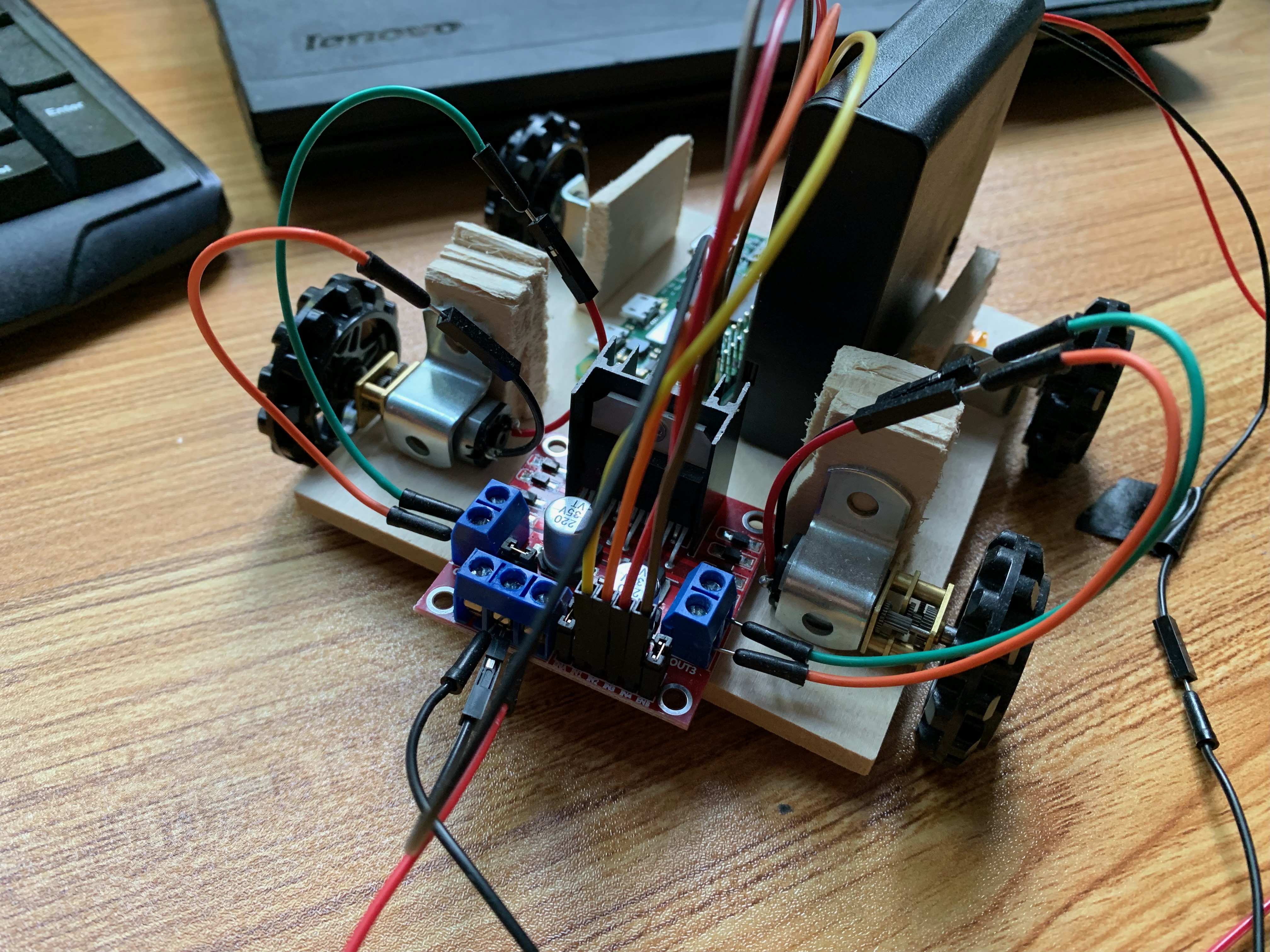
Because this was a prototype, I went to my local Michaels and just bought a couple of lightweight pieces of wood. Essentially a step above balsa. I cut off a rectangle that I figured would be about the right size and set about figuring out how to attach the wheels. As mentioned previously, this is where I REALLY wished I had bought the motor mounts because my solution of metal brackets, Krazy glue, and wooden backstops was, shall we say....janky.
By the time I attached the brackets and put all the leads in the right place, this is what things looked like:

Current Events
Get it? Current events?? Don't even get me started on the rest of my computer engineering puns circuit. Halp.
In all seriousness, up to this point I'd been using the Pi's onboard power supply to run the motor driver. That setup is fine if you're blinking LEDs or spinning a frictionless motor, but to actually have this puppy start generating some torque, I knew I needed more power than the onboard supply could provide.
Enter the External Power Supply. I went back and forth on what was a reasonable setup for this. Most of the projects online use something like the ICR18650 Lithium cell...which was admittedly a little hardcore for me given the money I'd already sunk on this project. I ended up going with a standard 4 AA powersupply which is a lot easier but not exactly easy on the eyes or particularly space efficient. For a later iteration of this project, I would definitely look into one of the rechargeable Lithium cells.
With the battery pack installed, I could tell the motors were definitely generating more torque - enough that the simple spin_wheels.py program above actually caused the robot to inch forward. Sweet.
Moving Forwards
At this point, certain life events caused me to sideline this project for the time being. I'd love to come back to it at some point and continue to develop it further. For now though, I've got a little robot that can execute predefined Python scripts - on the whole, not a bad showing for an initial prototype.